NxStage Medical
Background
During my first co-op at NxStage Medical, I worked as a mechanical engineer in the product development team focused on peritoneal dialysis, a type of treatment for patients with loss of kidney function. I was tasked with designing an accessory to mount a piece of equipment to their mobile dialysis system.
Design Constraints
The accessory had to be easily installed and uninstalled by the user while also supporting the 5+ pound weight of the equipment. Typical dialysis patients have limited strength and dexterity, so ease of use was a major priority. The primary accessible point of engagement allowed was the table top geometry of the mobile dialysis system, which included a small recessed water channel. This project was also intended to be as low-cost as possible.
Concept Development
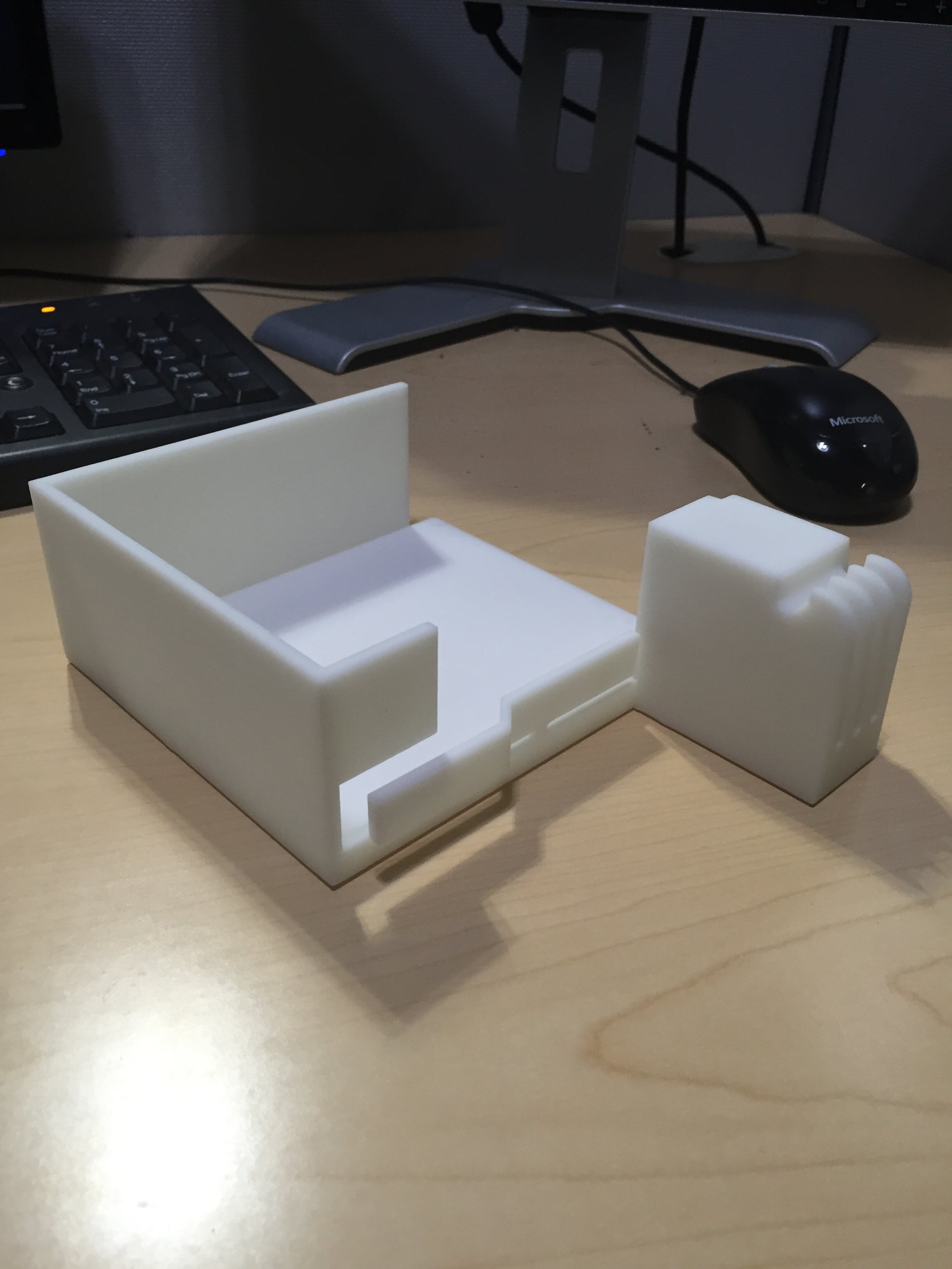
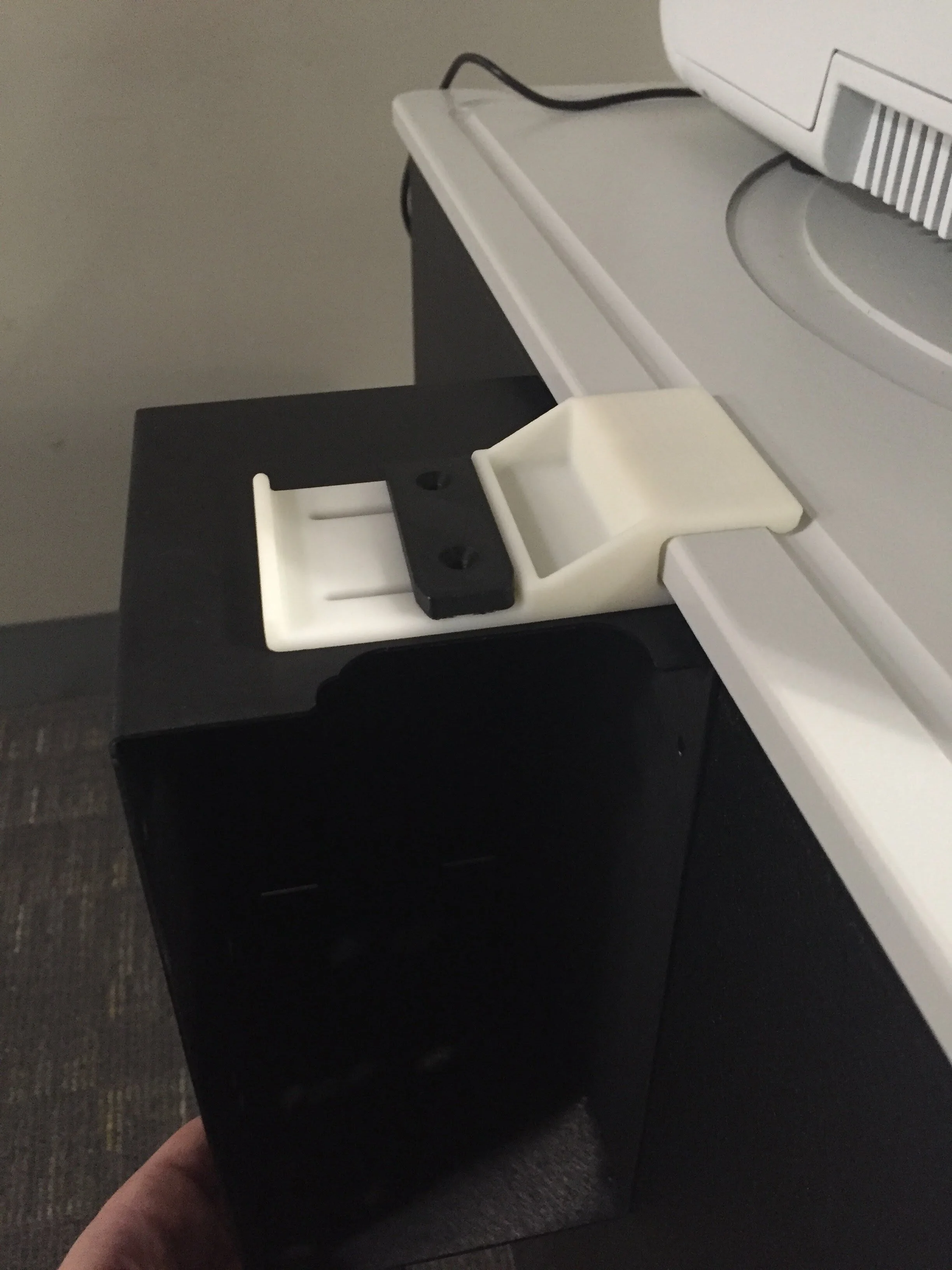
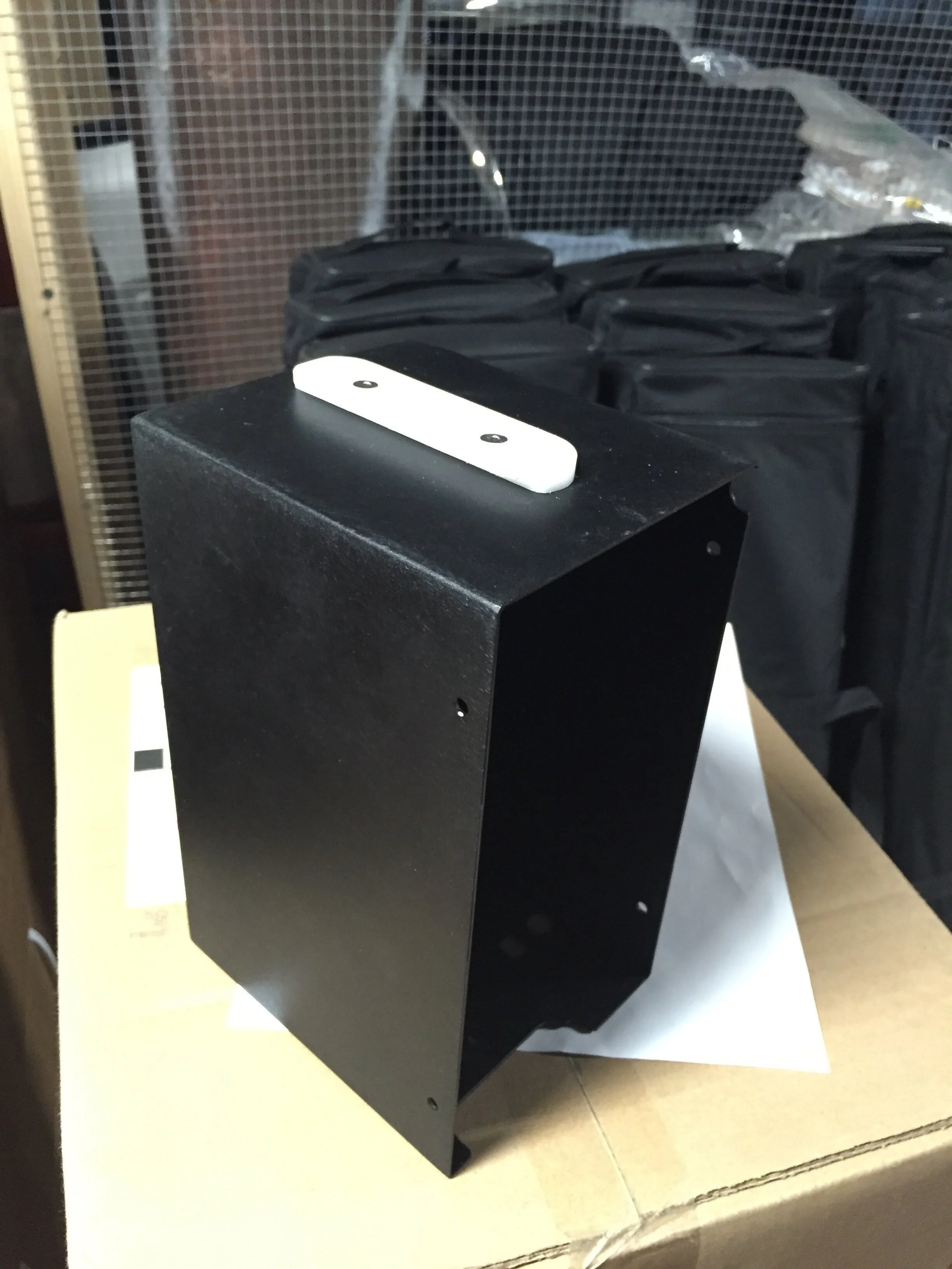
I iterated through over a dozen major design revisions, exploring a wide variety of installation methods to the equipment (black box shown below) and methods of attachment to the edge of the mobile system. I outsourced multiple 3D printed prototypes made using both FDM and SLA. Prototype assemblies ranged from one to four parts, with some utilizing heat set threaded inserts and machined attachments for the equipment. All 3D printed prototypes were designed in CAD for injection molding.



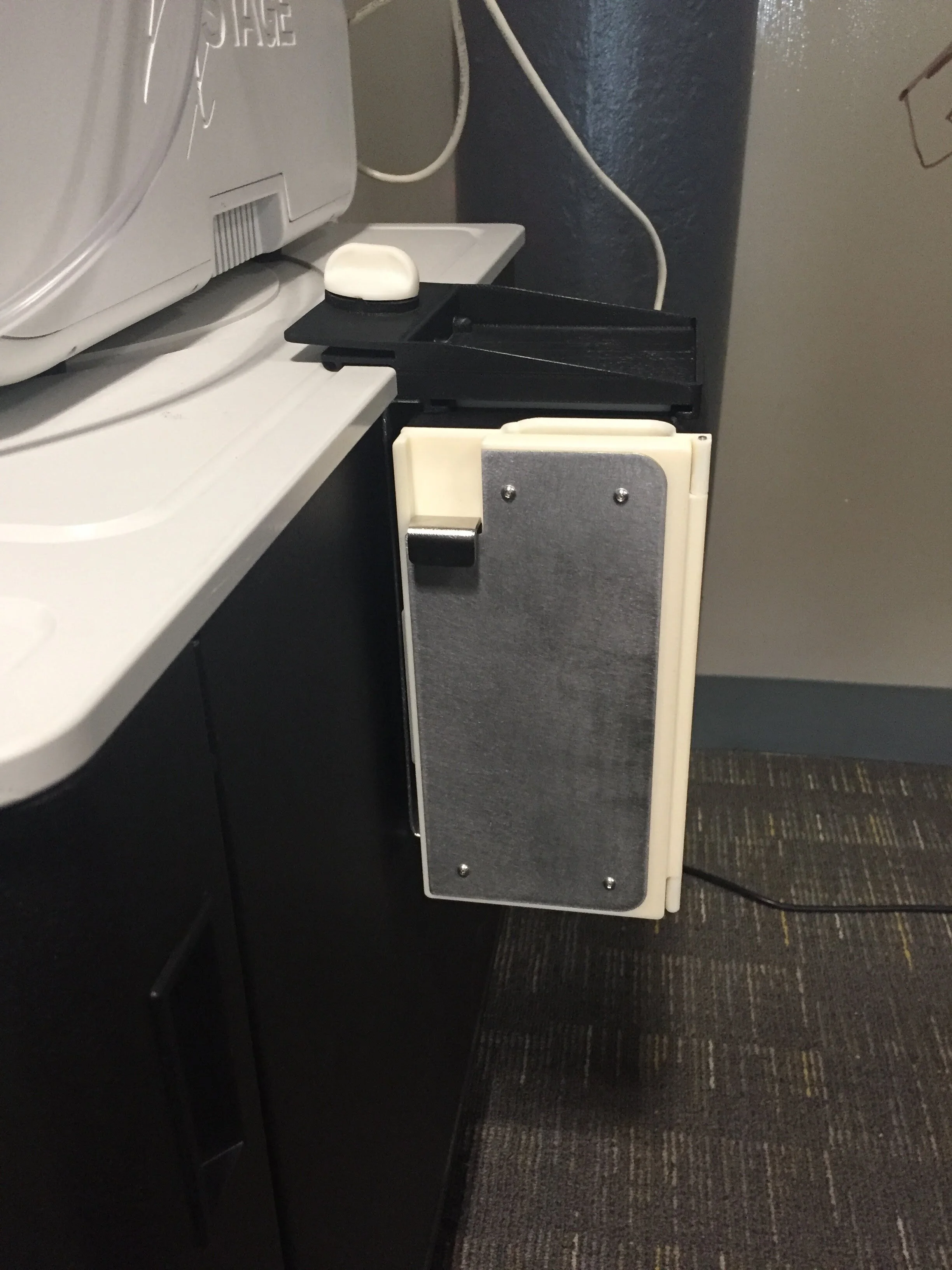
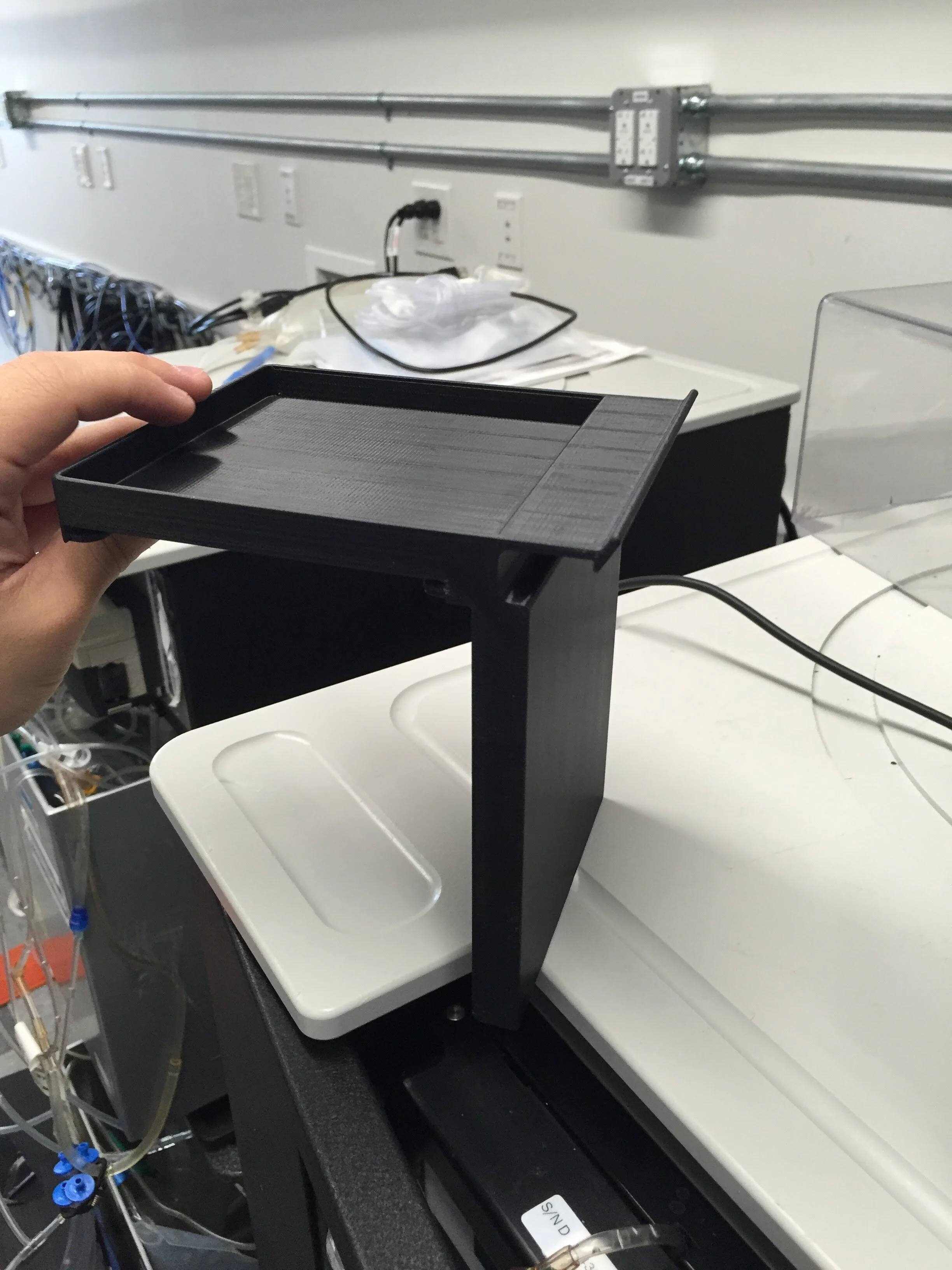
Design Overview - Threaded Clamping Knob Revision
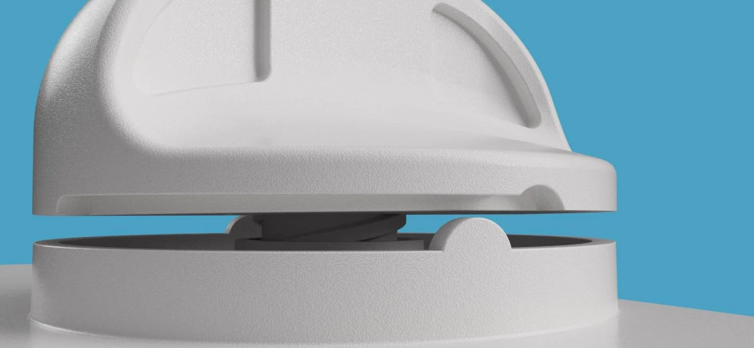
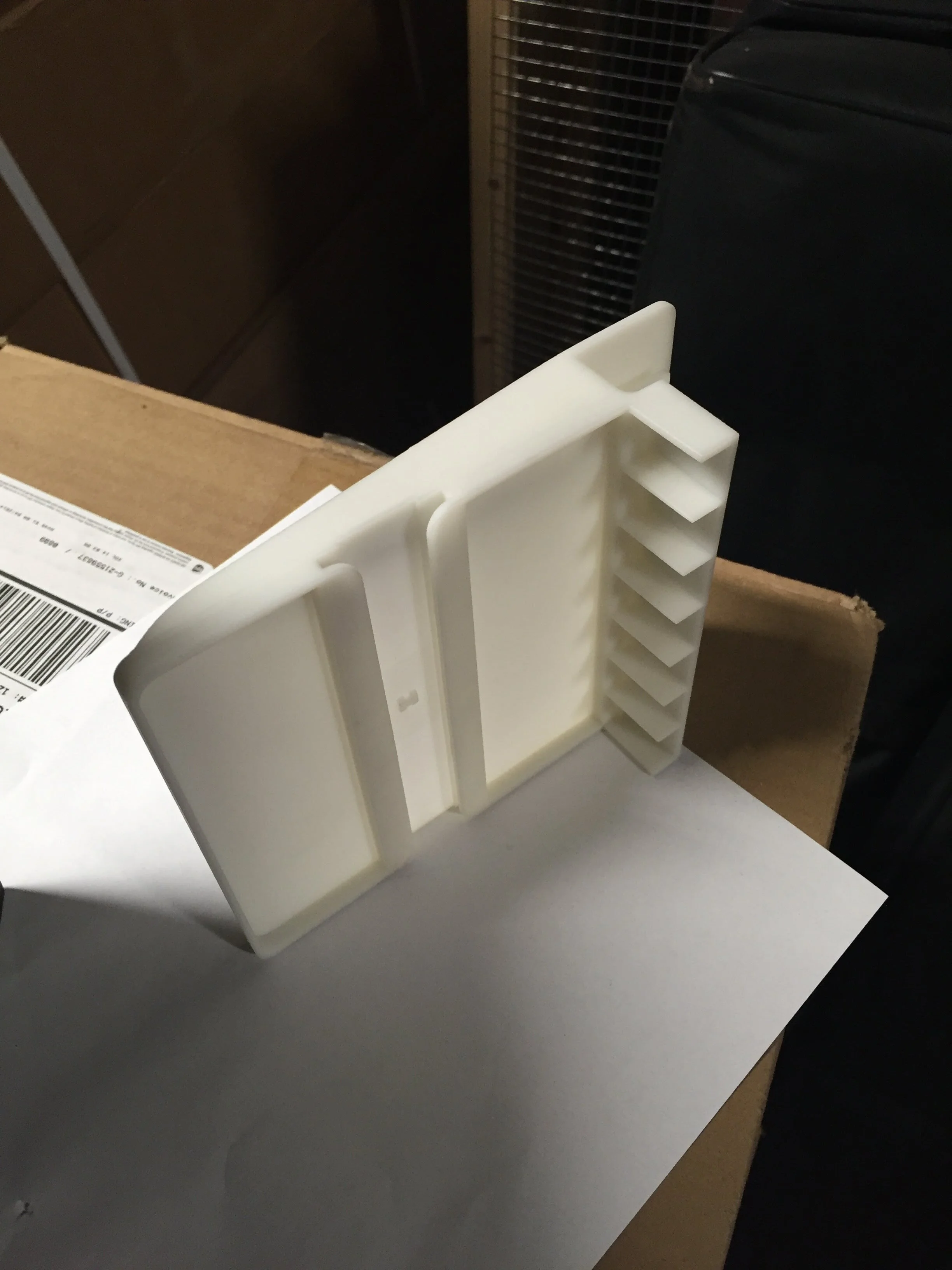
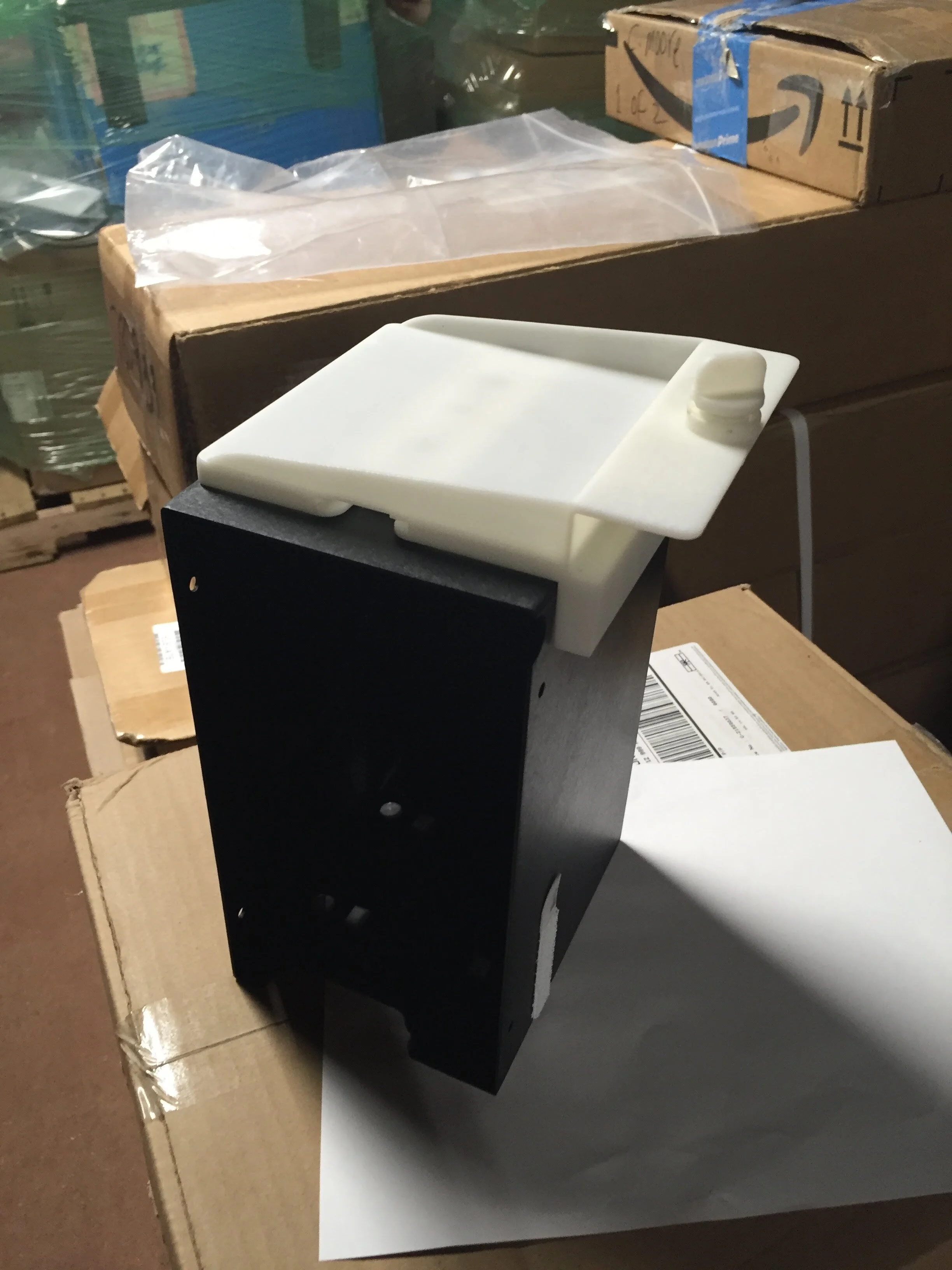
For this specific revision, I designed a two-part accessory for injection molding that engages with the table top shape of the mobile system and includes a rail geometry to mount the equipment. The accessory also features a threaded knob that when fully turned, clamps down onto the edge of the mobile system. The knob has a locking bump feature to give the user tactile feedback once the knob is fully engaged. This allows the accessory to be easily installed and removed by adjusting the degree of retainment with the knob.
Design for Injection Molding
The recessed cavity for the knob locking feature extends as close as possible to the knob's parting line without passing in order to maintain moldability and maximize bump height. The cost of the knob itself is greatly reduced by removing the two sides of the threads to allow two clean directions of pull. Recesses on the knob handle were created for comfort, but also to maintain nominal wall thickness. In the center of the rail are two small bumps that engage with the equipment when mounted, and are manufactured by two side action slides within the mold. The clamping geometry that mounts to the mobile system is made by the same slides, however the parting line is offset from the center to avoid a three-directional steel contact between the two slides and the threaded pin directly above them.
Final Prototype Demo
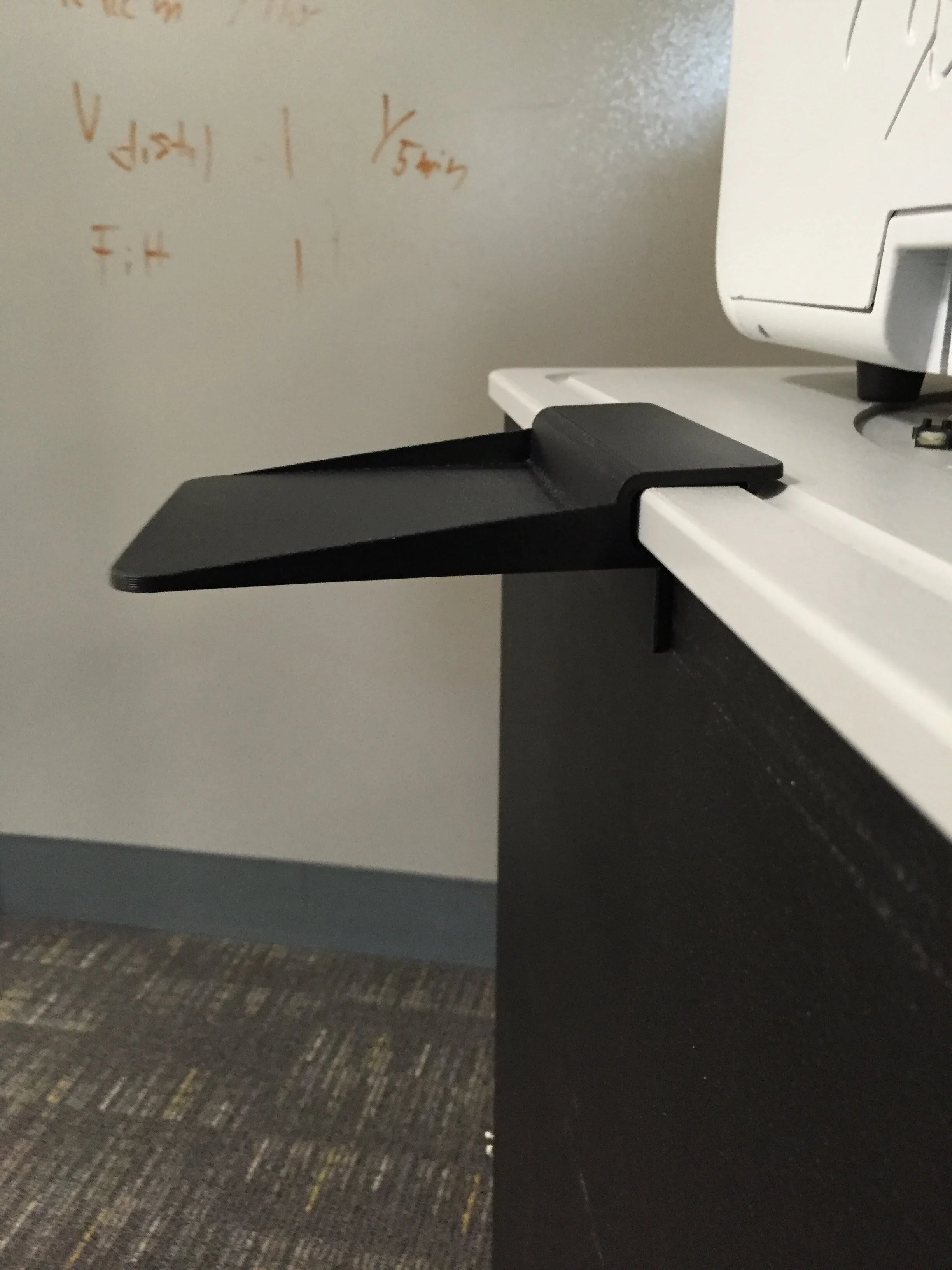
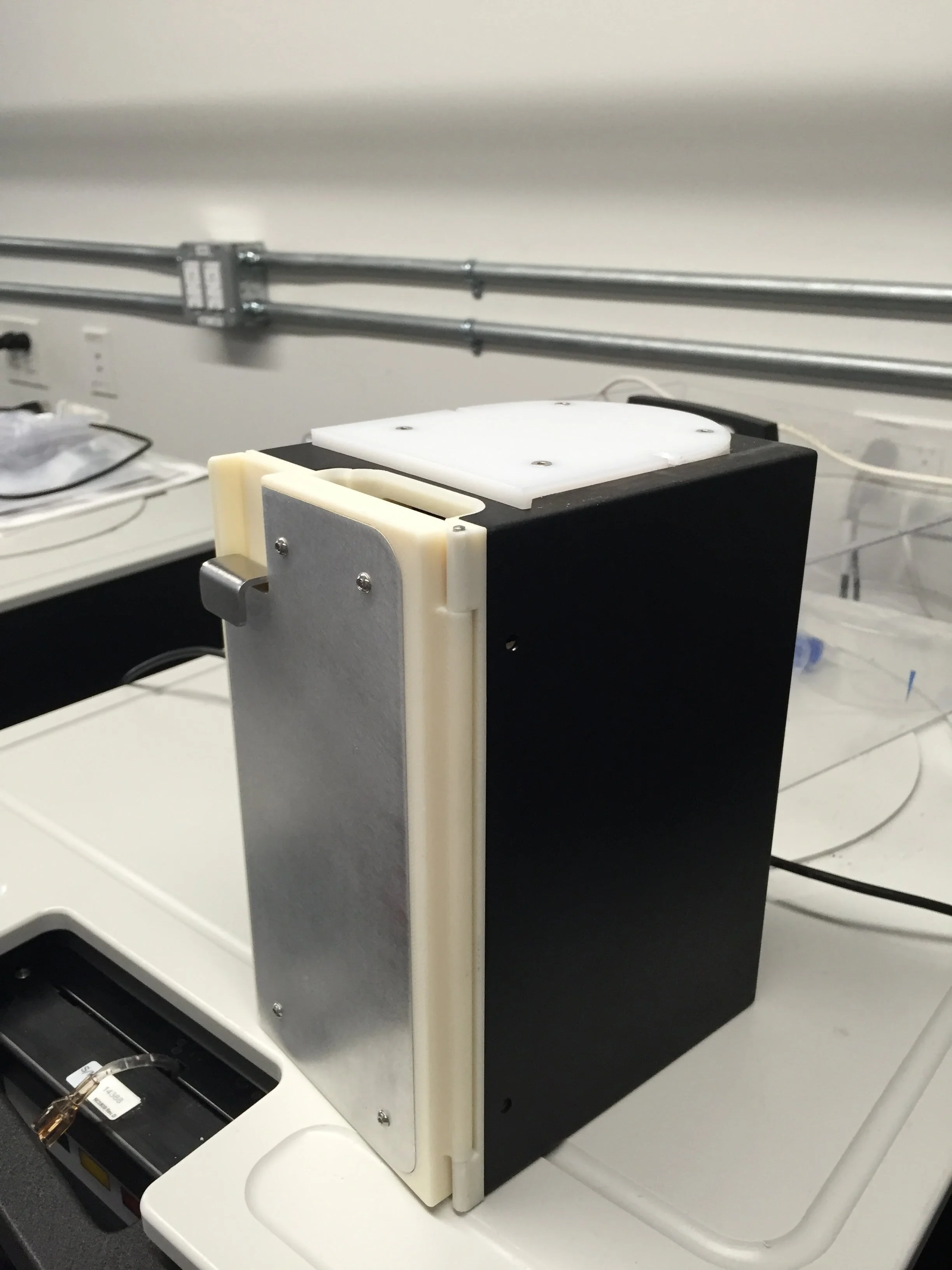
The final design for this project ended up not requiring the threaded clamping knob at all. Through each of the different design revisions, the geometry directly gripping the table edge and water channel was fine-tuned, and a large wall was added that proved key in providing increased structural rigidity to the accessory.
Key Takeaways
This project gave me a much stronger understanding of design for injection molding and how clever design choices can maintain functionality while reducing tooling cost. I had the opportunity to work with multiple vendors through prototyping and DFM phases to compare quotes and discuss manufacturability in order to optimize the design and present the most cost-effective solution to my team.


